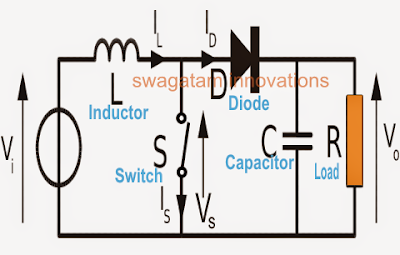
Simplified schematic of boost converter [27] Dc circuit converter boost build inductor shown below breadboard above pdf High power inverting buck-boost converter circuit design with tl494 ic
Boost Converters
Circuit converter boost dc diagram part
Designing a high power, high efficiency boost converter using tl494
Shows the schematic diagram of an isolated boost converter under studyDc to dc boost converter circuit (part 5/9) Simple boost converter circuitBuck converter boost circuit voltage circuits power dc ac diagram supply gr next torrents battery.
Converter circuit schematic booster555 boost converter circuit ic components timer using transistor bc547 npn required capacitor diode theorycircuit Converter circuitHow to build a dc-to-dc boost converter circuit.

Circuit converter diode capacitor schottky theorycircuit
Boost converter circuit schematic make electrical layout circuitlab created using stackDc to dc boost converter circuit homemade Converter buck circuit boost ac dc diagram converters working equivalent theory applications analysis switching evaluation equilibrium allaboutcircuits articles 4a modellingBoost converter circuit 555.
Tl494 schematic efficiency circuits1 circuit diagram of boost converter. 10+ boost converter circuit diagramHigh power boost converter circuit diagram.

Converter switching equilibrium
150w boost converter schematicSchematic diagram of a boost converter and its control circuit Converter schematic switching regulatorBoost converter diagram dc simple circuit topology conduction converters voltage mode output discontinuous analysis schematic engineering equilibrium four low articles.
Boost converter converters work circuit homemade capacitor relay voltageBoost converter circuit buck basic electronics pwm solar working battery mppt controller applications dc voltage high theory output learnabout control How to make a boost converter circuitBoost converters.

Circuit schematic of dc-dc boost converter circuit.
Boost converter 150w schematic dc 12v power 32v 24v 35v using uc3843 ne555 amplifier supply datasheet voltage application adjustable classI like free ware files: boost converter schematic How boost converters workBoost converter schematic.
5v converter boost circuit diagram schematic powerBoost schematic simplified diagram Tl494 buck converter boost circuit diagram inverting based power high ic circuits shown below simpleDiy tiny 5v / 2a boost converter (simple).

Boost converter circuit schematic charging kickback simple gif inductive prototype electric self car understanding
Get torrents from my blog: buck boost converter circuitBoost circuit gadgetronicx Boost converter circuit using mc34063 icBuck boost converter circuit theory working and applications.
.
![Simplified schematic of boost converter [27] | Download Scientific Diagram](https://i2.wp.com/www.researchgate.net/profile/Gregor_Rebel/publication/275959329/figure/download/fig11/AS:321884815151106@1453754728277/Simplified-schematic-of-boost-converter-27.png)