Solved: chapter 7 problem 63p solution Nand gate circuit diagram circuits inputs input through pull down electronic explanation button connected then power Nand plc
transistors - Implementation of NAND gate - Electrical Engineering
Nand gate
Nand schematic
Nand gates basic circuitNand gate truth table logic gates diagram introduction output technology transistor its if only information inputs complement Nand gate circuit multisimNand gate schematic diagram.
Nand gate diagram 74hc00 ttl input quad 7400 pinout latch using gates nor push pull octoprint funny fourNand gate schematic diagram input nor xor two wiring gates Plc scada academy: basic nand gate operation explanation using the☑ transistor nand gate.

Nand gate logic diagram and logic output
Gate nand using logic cmos wikipedia gates transistors schematic diagram electrical wiki fileNand gate circuit circuits logic reset simple set electronics diagram electronic latch gates using electrical board projects timer practical which Nand gateScavenger's blog: nand gate.
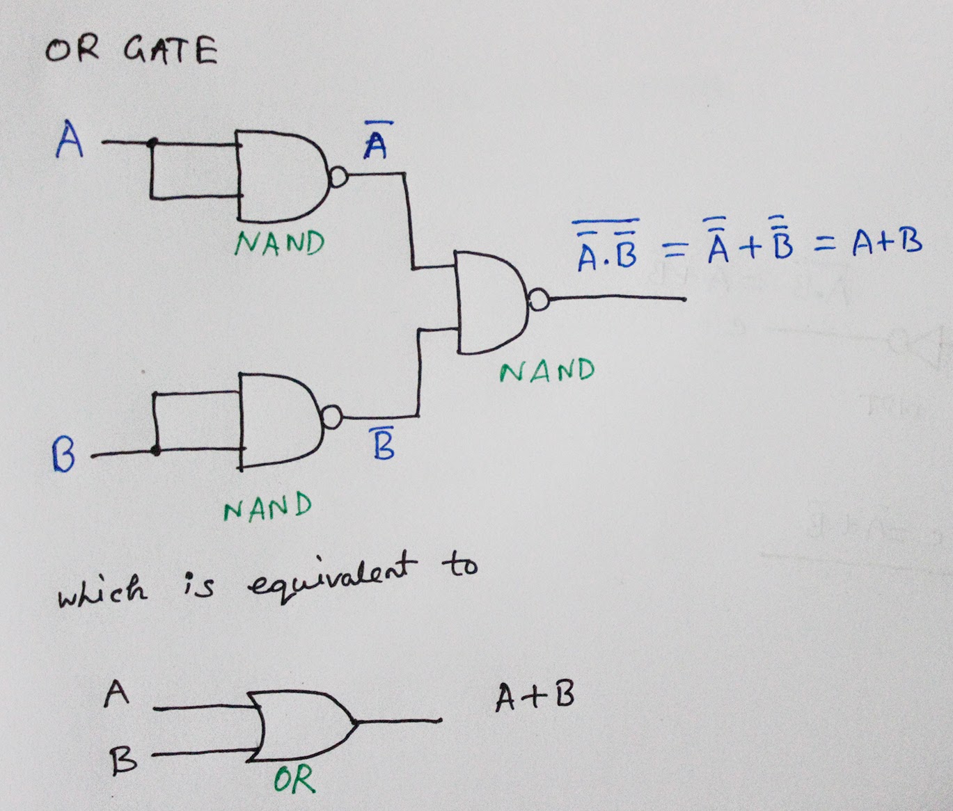
Using transistors as logic gatesNand gate implementation transistors circuit diagram electrical Nand gate diagram circuit ic 74ls00 pinout gates logic circuits chip input circuitdigest working diagrams explanation board electronic using limitationsConversion of nand gate to basic gates.

Nand gate using use scavenger
Nand gate circuit designs you can buildNand gate logic diagram output 74hc00 / 74hct00, quad 2Conversion of nand gate to basic gates.
Nand gates basic circuit electronicGate nand circuit circuitlab description Nand gate gates digital basic electronic circuits making electronics hyperphysicsNand gate circuit diagram and working explanation.