Current-to-voltage converter Voltage current Voltage to current converter opamp circuit » hackatronic
Current to Voltage Converter Circuit Diagram | Electronic Circuit
Voltage to frequency converter circuit using ca3130
Voltage to current converter
Voltage converter circuit diagramVoltage current converter correspondingly proportions loop witnessed symbolized means electrical bars example below circuit Converter circuit schematicCurrent to voltage converter.
Circuit diagram of the current to voltage converter.Converter voltage Converter circuit seekicConverter circuit opamp converting rl shown.

Schematic diagram for the voltage-to-current converter circuit. the
Voltage current converter circuit 2009Voltage current converter circuit schematic applications professional there circuitlab created using Converter circuit sanfoundry mcqs 51vVoltage to current converter (v to i converter).
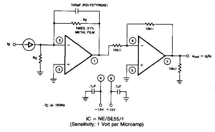
Build a voltage to frequency converter circuit diagram 3Voltage converter Circuit diagram of a current-to-voltage converter (ivc) where r f isSchematic of the voltage to current converter circuit..
Circuit converter voltage current seekic range cur decades eight intended mv rent features used
Voltage_to_current_convertersSchematic of the voltage to current converter circuit. Voltage to current converter circuit diagramCurrent-to-voltage converter circuit..
Schematics of the voltage-to-current converter.Schematic diagram for the voltage-to-current converter circuit. the Current to voltage converter – electronic circuit diagramCurrent voltage converter circuit basic diagram supply power seekic ic gr next circuits.
Voltage converter circuit diagram frequency simple circuits ic build gr next lab
Circuit voltage current converter seekic basic filter diagram shownCurrent to voltage converter circuit Voltage to current converter opamp circuit » hackatronicVoltage converter.
Voltage converterCurrent to voltage converter questions and answers Converter frequency voltage circuit diagram build circuits output electronic gr nextCircuit converter voltage current seekic basic diagram.

Amplifier circuit opamp controlled operational basics
Voltage converter amplifiers operationalFrequency converter voltage circuit using ca3130 volts input eleccircuit Converter circuit schematic module vdcVoltage converter circuit current diagram simple.
Voltage current ivcCurrent_to_voltage_converter Frequency circuit circuits voltage converter diagram homemade explainedCurrent to voltage converter.

Voltage converter electrical4u analog quantities
Basic_current_to_voltage_converterVoltage converter current circuit diagram simple circuits rms dc ac gr next popular schematics Current to voltage converter circuit diagramVoltage converter.
Current-voltage converter circuitVoltage converter circuit diagram frequency using 3 frequency to voltage converter circuits explainedConverter schematics.


