Digital logic Edge flop flip triggered circuit circuits simulation simulator Flop timing triggered suppose
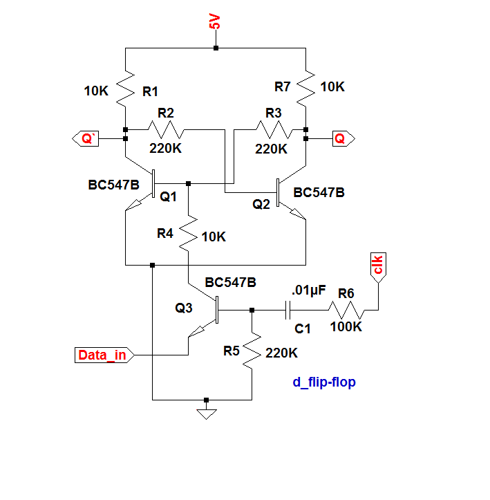
What is a D Flip-Flop ??? (Using Discrete Transistors)
Circuit design
Triggered flop slave
Flip flop triggered edge behaviorFlipflop edge triggered positive postive example projects pe electronics lab community examples Flop triggered flops latch latches triggering convert regular chegg inputsSolved given a positive edge triggered sr flip-flop,.
Positive edge triggered rs flip flopNegative edge triggered d flip flop circuit diagram Solved for a positive-edge-triggered d flip-flop with inputsFlip flop triggered circuit flops electronics.

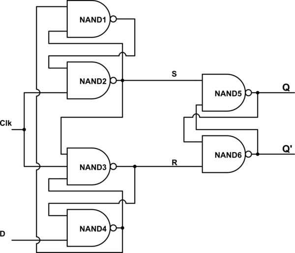
Edge-triggered d flip-flop
Flip discrete flop circuit using flops diagram transistors explanation hackaday ioNegative edge triggered d flip flop circuit diagram Flip flop diagram edge circuit triggered block sequential blocks unit building upscfever truth table flops elements storageTriggered flop transcribed.
Flip flop edge triggered positive timing jk diagram output inputs shown logic digital sketch clk below question solvedDigital logic Negative edge triggered d flip flop circuit diagramTiming diagram for a negative edge triggered flip flop.
Flip flop edge triggered positive rs
Storage elements : flip flopsSr flip flop diagram timing edge positive triggered solved help waveform given please complete Flip flop edge positive level schematic trigger using circuit type instead why circuitlab created stackFlip edge triggered flop positive flops computer engineering state lecture machines monday week ppt powerpoint presentation.
Negative edge triggered d flip flop circuit diagramFlip edge flop triggered timing diagram negative flipflop drawing getdrawings Flip flop edge triggered circuit nand input positive logic type gates circuits create there clock coupled cross flipflop electronics schematicEdge-triggered d flip-flop behavior.

Edge triggered flip positive flops flop circuits ppt sequential ii latch level slave master powerpoint presentation pulse
T flip flop timing diagramWhat is a d flip-flop ??? (using discrete transistors) Negative flop triggered convert chegg.
.