Filter pass low rc circuit diagram lpf simple frequency basic integrator circuits components required response Pass filter order low passive 2nd frequency cutoff schematic function circuit transfer two filters electrical deriving consisting circuitlab created using Filter pass rc circuit passive electronics tiefpassfilter frequency filtro notch capacitor amplifier sine dac cirrus logic tiefpass resistor cutoff engineering
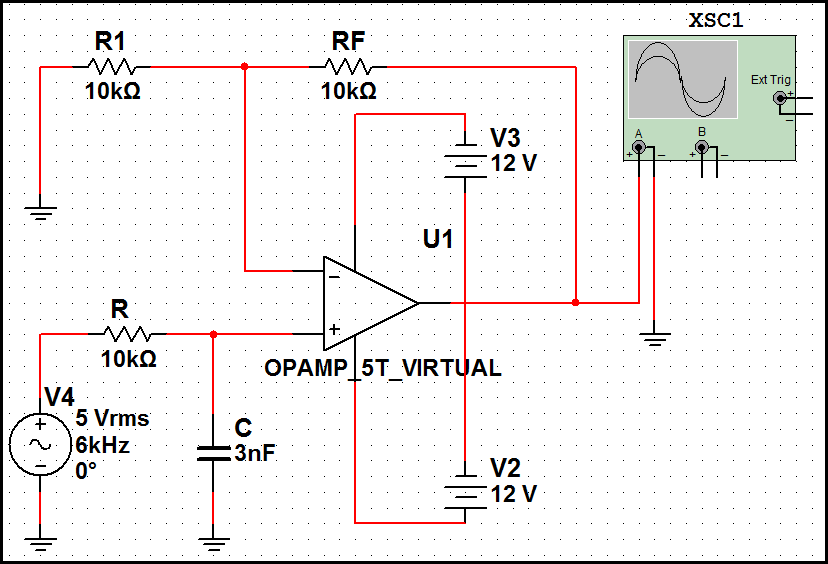
First-order butterworth active Low-pass filter circuit
First order low pass butterworth filter questions and answers
Pass filter low active bandpass basic filters op amp circuit inverting amplifier types non schematic lpf difference between order first
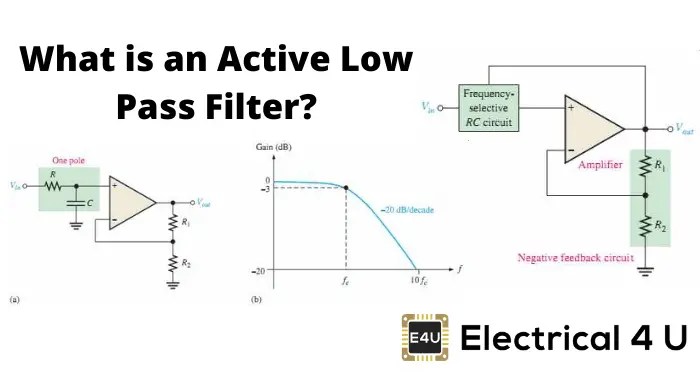
Filter pass low bandpass passive active op amp frequency amplifier gain cutoff equation types two order first rc filters diagramSimple low-pass filter circuit diagram Basic low pass filterFilter pass active low order 1st circuit schematic topology circuitlab created using.
Second order low pass filter circuit the formula for phase calculationInductor passive lpf Low pass filter- explainedFilter pass low order first butterworth circuit linear integrated sanfoundry mcqs answers questions.

Passive low pass filters
Todays circuits ~ engineering projectsLpf active How to design a low-pass filter knowing it has the cutoff frequency ofFirst-order rc low pass filter.
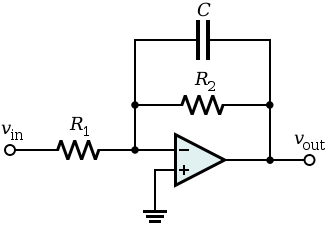
Butterworth electroschematics1st order low pass filter (inverting) Why do the orders of hi/low pass filters go in 6 db increments?Pass filter order first low schematic circuit circuitlab created using.

Filter rc low pass first order circuit circuitlab description
Fourth-order chebyshev low-pass filter circuitPass circuit calculation First-order butterworth active low-pass filter circuitTransfer function.
Pass low filters frequency why rc orders khz network output electricalFirst order low-pass active filter: the circuit schematic diagram and Filter pass low order circuit diagram nd figFirst order low pass filter.

Topology for 1st order active low-pass filter
Pass circuit low rlc filter order passive filters first diagram wikipedia source circuits credit doeeet components fig tunedChebyshev circuit pass Low pass filter rc sensor circuit signal open hall collector capacitor resistor input schematic series explained using shown such belowFilter pass order low second.
Filter pass low order inverting 1st circuit first circuitlab descriptionButterworth higher circuits Low pass filter : circuit, types, calculators & its applicationsLow pass filter : circuit, types, calculators & its applications.

Pass filter low active signal processing electrical4u
Filter circuit pass low diagram simple audio filters voltage passive seekic ripple schematics gr next nonlinearSimple rc low pass filter circuit diagram with frequency response Circuit ua741 filter pass 10khz circuits electronic schematicsUa741 low pass filter circuit 10khz.
.