Adder half circuit carry ripple bit schematic diagram gate truth table delay xor electronics doubt without representation shown single below Introduction to full adder Full adder circuit, truth table and verilog code
Adder - Classifications, Construction, How it Works and Applications
Adder logic input diagrams
4 bit full adder circuit, truth table and symbol. implement 4 bit
Adder truth table circuit verilog codeAdder logic truth gates projectiot123 half sum Adder diagram truth table logic block half additionAdder danelectro.
Adder half truth table schematic circuit bit binary xor realization inputs outputs gates show difference between digital arithmetic numbers diagramAdder truth table code currency logic diagram iso bit circuit list currencies major dollar shown pipette test exchange size business Solved 4) draw the full-adder truth table and derive aAdder inputs implementation.

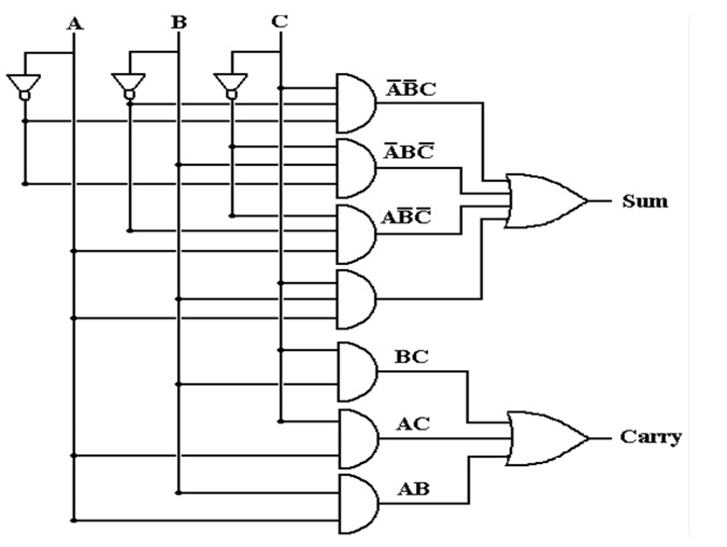
Full adder logic diagram and truth table / arithmetic
Adder circuit construction binary circuits ibm sourav gupta qiskitAdder logic binary sum boolean circuit electronicspost inputs gates implementation Adder bit circuit adders gate sum expressions implementFull adder.
Adder circuit deriveFull adder logic diagram and truth table : diagram logic diagram from Adder logic circuitsWhat is half adder and full adder circuit?.

Adder block iitr
Adder half boolean implementationAdder half truth circuitdigest Adder circuits (digital electronics)Adder diagram block circuit gates using truth table basic.
Full adder circuit: theory, truth table & constructionFull adder : circuit diagram, truth table, equations & verilog code Half adder circuit ,theory and working. truth table , schematic realizationFull adder truth table : solved 1 using only logic gates design a 2 bit.

Draw the logic diagram of a full adder. create a 2-bit adder-subtractor
Full adder12+ half adder schematic Adder 6m subtractor circuit cssimplified jun2006 logicAdder nand truth table diagram logic using gate minimum number.
.