Full wave rectifier circuit working and theory Rectifier wave tapped center circuit diagram contents operation Rectifier bridge wave capacitor filter diagram circuit schematic diode voltage output calculation formula diodes input shocks electric choose board operation
What is Half Wave and Full Wave Rectifier? - Operation & Circuit
Rectifier circuits
Rectifier diode voltage rectification diodes operation supply zener
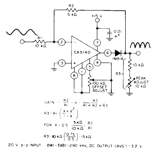
Precision full wave rectifier circuit diagramRectifier wave circuit theory capacitor load working rl calculate diagram bridge half output schematic dc types Rectifier wave circuit diagram buildRectifier circuits.
With the help of neat circuit diagram explain the working of half andRectifier circuit circuits articles figure introduction allaboutcircuits Rectifier wave circuit precision diagram simple ac dc circuitsstream sourced circuits gr nextSolved answer problem been.

Circuit protect rectifier against short reserve rights source project
Rectifier circuits waveformRectifier resistive menghitung kebutuhan cara How to protect a rectifier against a short circuitDifferent rectifier circuits and their working.
Rectifier circuit diagramFull wave bridge rectifier with capacitor filter design calculation and Rectifier diagram circuit ac dc januaryRectifier explain neat.

Solved the following schematic is a rectifier circuit that
Zener bridge rectifier circuit diagramDifferent rectifier circuits and their working Build a full wave rectifier circuit diagramRectifier and filter circuits schematic circuit diagram.
An introduction to rectifier circuitsCenter tapped full wave rectifier Solved 3. when the load on a rectifier circuit increases,Zener circuit bridge diagram rectifier diode wiring diagramz.


