Circuit diagram camera charger batteries cameras security digital color circuits wiring lm317 electronic power psu gr next archive choose board Timing circuit diagram chegg complete solved transcribed text show adder clk Control diagram motor wiring circuit line elementary figure electric draw power fig shown bartleby chapter
Solved Question Pre-2: a) The two circuits diagrams in | Chegg.com
Solved question pre-2: a) the two circuits diagrams in
In the circuit of the figure below determine the current
A wire is joined to points x and y in the circuit diagram shown. howSegment scoring breadboard Circuit diagramsCircuit wire diagram shown points change does when joined added.
Identical figure diagram solved shown transcribed light text show bulbs brightness circuit bulb predictHomework ii Solved 6. in the circuit shown in figure 1, the voltmeterIn the circuit diagram shown below,what is the reading of ideal ammeter.
Circuit diagrams
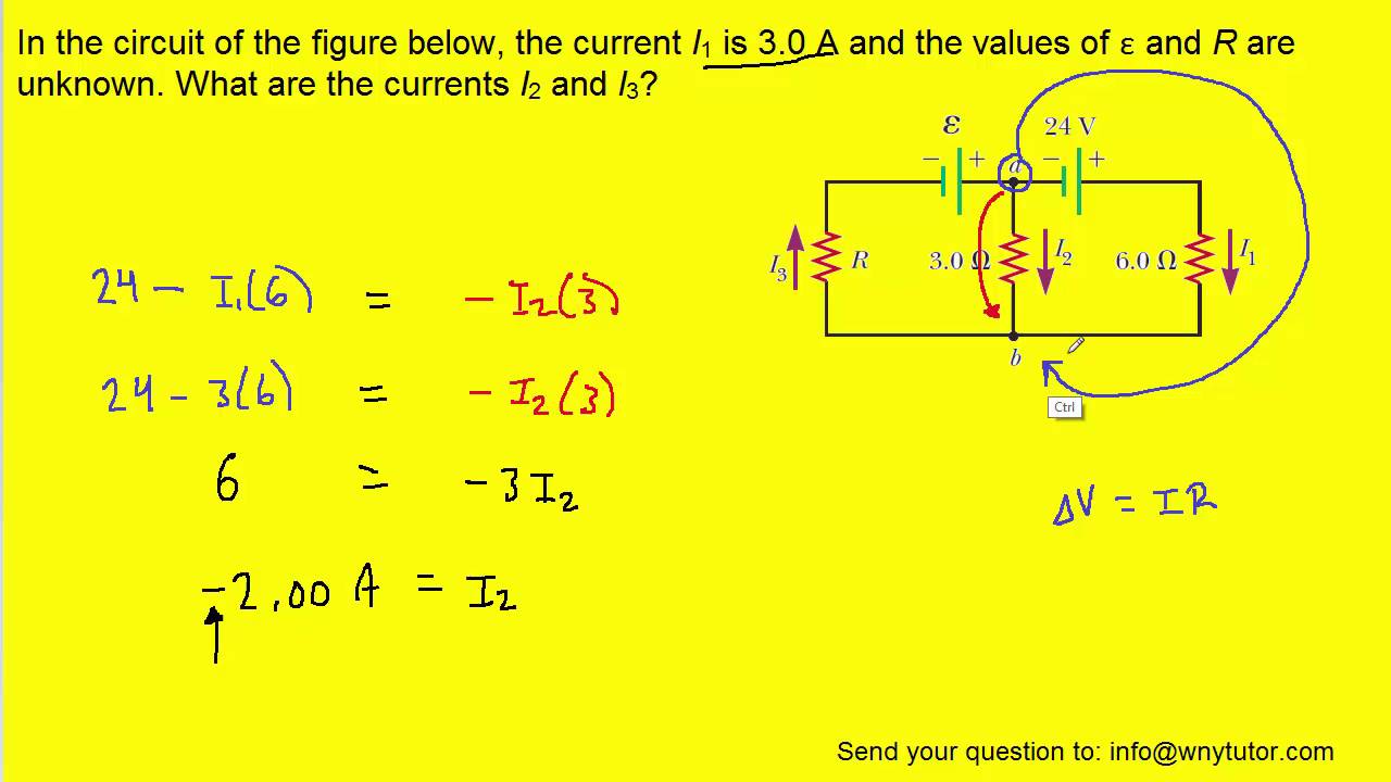
Solved calculate the three currents i1,i2 and i3 indicatedCalculate currents three indicated p26 In the circuit of the figure below, the current i1 is 3.0 a and theDraw an elementary line diagram of the control circuit from the wiring.
Jamal draws the circuit diagram shown. there are three light bulbsCorresponds circuit shown diagram logic gate answer correct Voltmeter voltageCircuit current i1 below figure unknown values.

Circuit branch current shown each determine figure
Circuit current determine below figureSolved for the circuit shown in the figure (figure 1), find Solved complete the timing diagram of the circuit shownCircuit diagram alternatives and similar software.
Circuit diagram software alternativetoElectronics circuits diagrams Corresponds diagram logic circuit gate shownCircuit diagram for program counter.

Three shown diagram bulbs draws jamal circuit light there
The circuit diagram shown here corresponds to the logic gate .
.