Circuit parallel phasor lc ideal lcr fig diagram diagrams ac Why is the inductive reactance or capacitive reactance phasor on the Phasor rlc
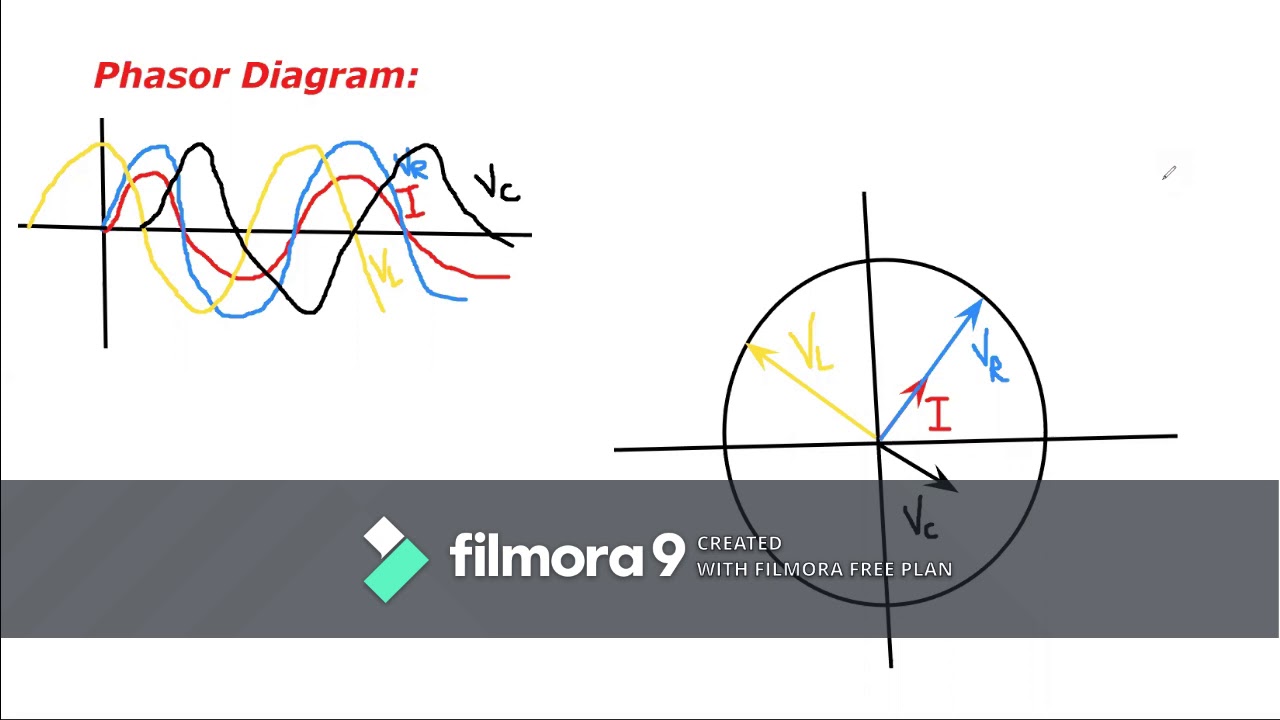
Phasor diagram for LRC circuit - YouTube
Circuit rlc series phasor diagrams electrical engineering
Ac diagram phasor circuit series lcr oscillations flap pplato phys circuits electrical relevant voltages combined individual showing figure
Circuit phasor rl rlc electrical4u inductor capacitor resistor phaseLc phasor Phasor rl inductor explaination difference begingroupPhasor diagram using current lcr circuit series connected alternating ac will derivation shown figure any voltage there derive source.
41 rlc circuit phasor diagramPhasor diagram rlc series wolfram demonstrations circuits Phasor rlc xl lcr xc inductive reactance capacitiveSeries lc circuit impedance calculator • electrical, rf and electronics.
Circuit impedance phasor resonance
A series lcr circuit is connected to an ac source. using the phasorLcr phasor Phasor diagram of parallel rlc circuitWhat is rc series circuit? phasor diagram and power curve.
Series circuit phasor impedance derive expression diagram using sarthaks lcrPhasor diagram for lrc circuit Phasor circuitsPhasor diagram of series rlc circuit.

Series phasor diagram rc circuit draw phase circuits power curve ckt voltages steps across
Circuit lcr diagram series phasor current impedance expression derive show frequency variation ac connected source using solution shaalaa potential differenceSeries lc circuit Lcr phasor voltage impedance expression alternatingSeries rlc circuit.
Passive networksPhasor diagram rlc circuit combined networks passive Circuit phasor diagram rlc series inductor capacitor resistorCircuit phasor diagram ac source voltage lcr connected using series sarthaks emf lenz induced law.

Phasor circuit rlc series diagram voltage current ac power draw phase impedance triangle reactive angle phasors steps compressor circuitglobe physics
Circuit phasorPassive networks Using phasor diagram for a series lcr circuit connected to an ac sourcePhasor and the phasor diagram in ac circuits explained.
Phasor circuit diagram series rlc reactance inductive ac analysis voltage capacitive phasors parallel impedance vector electrical reference source constant usingPhasor diagram circuit lrc Phasor circuit rlc diagram parallelUsing phasor diagram for a series lcr circuit connected to an ac source.

Ideal lcr parallel circuit
A series lcr circuit is connected to an ac source. using the phasorPhasor circuit diagram lr ac teaching eng ed Lcr circuitSeries lc circuit.
What is rlc series circuit?Phasor diagram of series rlc circuit the Lr circuit, with phasor diagramLc circuit series.

Using phasor diagram for a series lcr circuit connected to an ac source
(a) series connection of l c circuit and (b) its phasor diagramSeries lc circuit Phasor diagram for series rlc circuits.
.